

Adding a custom peripheral to QEMU RISC-V machine emulation & interacting with it using bare-metal C code
Introduction
QEMU is an excellent platform to emulate hardware platforms. But, we often end up using ready-made platforms without thinking twice about how QEMU emulates them. This article dives into the depth of how a new peripheral can be added to an existing QEMU machine and how to interact with it using bare-metal C code. Ultimately, we will build a RISC-V machine that has our custom peripheral and driver for that peripheral.
Compiling QEMU and understanding the build system:
For detailed steps on setting up the tooling and compiling all the required pieces, refer to my previous article: Linux & Python on RISC-V using QEMU from scratch.
Before we add things to QEMU, we need first to understand the development ecosystem. I am compiling the latest 5.2.0 version of QEMU for this.
QEMU has a build flow similar to the autoconf tools based flow – we first do a configure and then make. However, recently, QEMU started using uses Meson build system under the hood instead of GNU autotools. The main difference we note at first is that only VPATH builds are supported. Configuration environment properties are identified by the configure script, recipes by Kconfig, Meson takes over at that point to tie together the build. Even though Kconfig is used, there is no UI to manage the configurations. This info will come in handy when we later add our peripherals into the machine emulation.
To build QEMU for the RISC-V machine,
git clone https://github.com/qemu/qemu.git
git checkout v5.2.0
cd qemu
mkdir build
cd build

../configure --target-list=riscv64-softmmu,riscv64-linux-user --prefix=$RISCV

make -j$(nproc) install
$RISCVis where we want the built images to be stored
Note that we are building the
softmmuversion as well as thelinux-userversion.
From the QEMU manual, we know that :
new targets and boards can be added without knowing in detail the architecture of the hardware emulation subsystems. Boards only have to list the components they need, and the compiled executable will include all the required dependencies and all the devices that the user can add to that board.
This is what we will leverage to add our first peripheral.
Executing bare-metal RISC-V C code in QEMU
We will use riscv-probe as the base to start executing bare metal code. From the official repo readme, we know that:
riscv-probecontainslibfemtowhich is a lightweight bare-metal C library conforming to a reduced set of the POSIX.1-2017 / IEEE 1003.1-2017 standard.libfemtocan be used as a starting point for bare metal RISC-V programs that require interrupt handling, basic string routines, andprintf().
We clone the repo and compile it with:
git clone https://github.com/michaeljclark/riscv-probe.git
the toolchain we compiled in the previous article was not compiled with
--enable-multilib.So, I had to recompile it.
The default did not build !!
So, I had to define riscv_excp_names and riscv_intr_names as extern to get it to compile. After digging around, I found that PR#9 fixes a whole bunch of these issues. So, I cloned the patch branch (patch1 of axel-h / riscv-probe) and used it instead
git clone <https://github.com/axel-h/riscv-probe.git>
cd riscv-probe
git checkout patch1
make
Then execute the “hello world” code in the 64-bit virt machine using:
qemu-system-riscv64 -nographic -machine virt -kernel build/bin/rv64imac/virt/hello -bios none
The
-bios noneoption is not present in the officialriscv-probedocumentation. But with newer QEMUvirtmachines, you need to pass this option since the bios FW is loaded by default, and this overlaps with our bare-metal code.
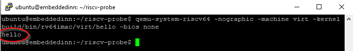
bare-metal hello world
Note added on
23-Jan-2022what is a
virtmachineThe virt board is a platform which does not correspond to any real hardware; it is designed for use in virtual machines. More information can be found in the QEMU Documentation page here.
Understanding the libfemto code flow
Here are the initialization and execution sequence of the riscv-probe femto ecosystem. This understanding is essential to generate a stripped out version of riscv-probe for us to use.
-
The C runtime (
crt.s->crtm.s) contains the_startsymbol that is the entry point to the C program post compilation. This function sets a generic trap handler and stack pointer and disables all hardware threads except hart 0. Next it calls ` libfemto_start_main()that is defined inlibfemto\arch\riscv\start.c` -
libfemto_start_main()initializes the memory required to load the C code as per the ABI and clears/inits the device handlers before callingarch_setup()and malloc memory initialization. -
arch_setup()is a platform-specific function that defines how the console and power-off sequence functions. For now, we will focus on thevirtQEMU machine for RISC-V that supports VirtIO.- This board’s UART console is based on ns16550a that is modeled in
libfemto/drivers/ns16550a.c. We will soon realize the reason behind why we are using this specific part.
- This board’s UART console is based on ns16550a that is modeled in
-
Finally, the
main()from our code will be executed.
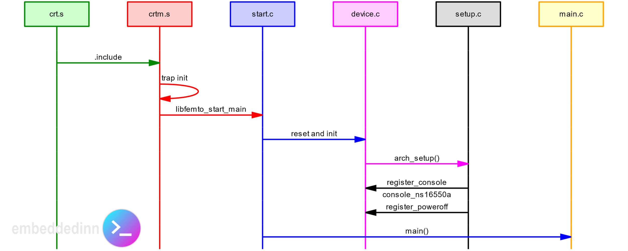
libfemto code flow
Stripping down riscv-probe
Since the Makefile is dynamic, we start by deleting all env components other than virt and common. Then I deleted all the examples other than hello and cleaned up the make file to build just the 64-bit hello program. For now, this is what we will use as our “SDK.” I can now modify and run bare metal code.
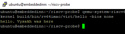
custom bare-metal code
Understanding the QEMU UART flow
In the previous experiment, we did a printf()—a relatively simple task in the application software realm. But, there are a few moving pieces.
From the fundamental code flow analysis, we know that UART is emulated after a ns16550a device. Let us see how a single character passed to printf() reach QEMU frontend. I am beginning this analysis with an assumption that finally, a character gets written into a memory-mapped register processed by the UART emulation in QEMU.
Here is the code flow of printf() within libfemto.
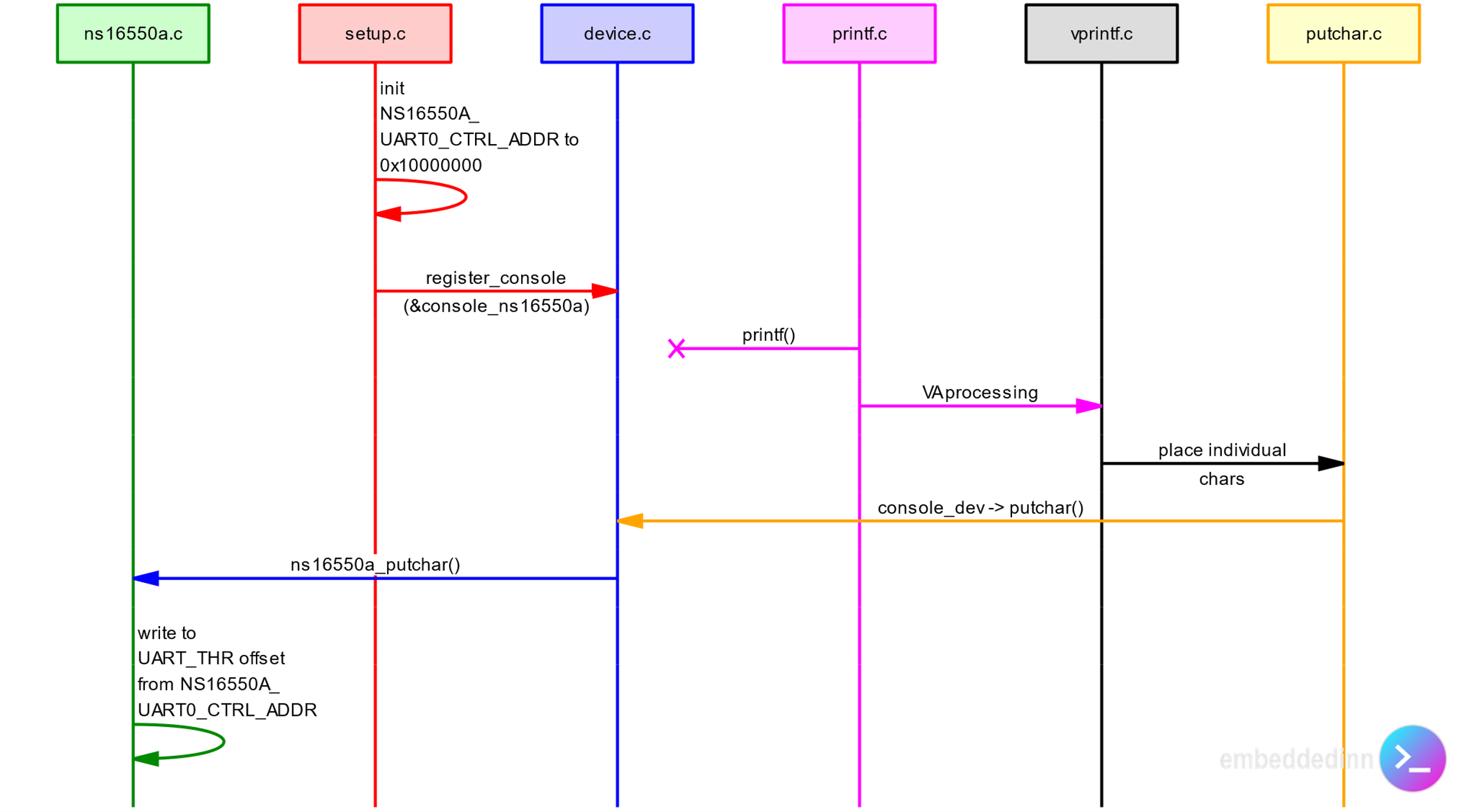
printf() code flow
The short version of the info present in the sequence chart is:
-
The
ns16550adriver inlibfemtowrites each character fromprintf()into address0x10000000, where the UART transmit hold register (UART_THR) resides. -
qemu\hw\riscv\virt.cfile mapsVIRT_UART0to the same address.
The QEMU serial device
Now, the question is, how does QEMU know that the contents of UART_THR have changed and that it needs to be printed on the console?
To understand this, we need first to understand how the UART device at 0x10000000 is mapped in QEMU. By looking at riscv\virt.c we know that the device is added as a flattened device tree (FDT). This info can also be pulled out of the pre-compiled QEMU instance by doing:
qemu-system-riscv64 -machine virt,dumpdtb=virt.dtb
dtc -I dtb -O dts virt.dtb \>virt.dts
More on this in the next section
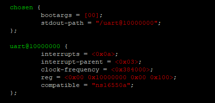
the QEMU device tree
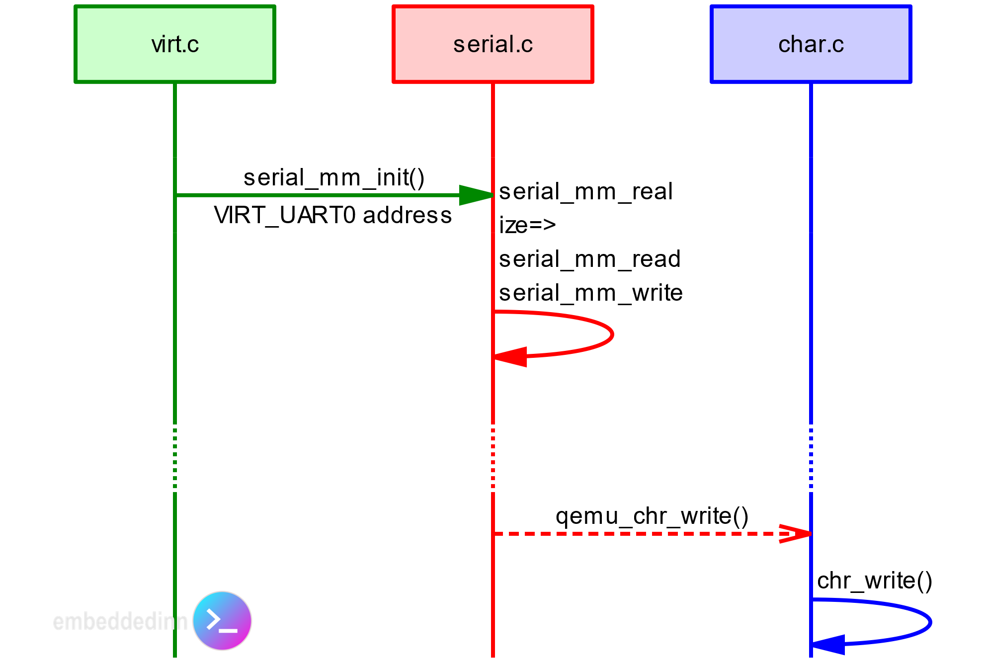
In virt.c, we also see a call to serial_mm_init() where the VIRT_UART0 address is passed on. Following this trail, we get to know how a printf() in the application code ends up in the emulated QEMU console.
-
As part of the
initfunction,serial_mm_realize()registersserial_mm_read()andserial_mm_write()functions as callbacks for I/O operations in theVIRT_UART0address range.- The function
memory_region_init_io()is used for this. This is in line with what the QEMU documentation says :
- The function
a range of guest memory that is implemented by host callbacks; each read or write causes a callback to be called on the host. You initialize these with
memory_region_init_io(), passing it a MemoryRegionOps structure describing the callbacks.
You can see this in action by passing the
-trace serial_ioport_writeflag while executing QEMU.
- Depending on the emulated register to which the write happens, ` serial_mm_write()
takes the relevant action. In case of a character to transmit, it callsqemu_chr_fe_write ()` that ultimately results in the character to be pushed out of the relevant console interface.
QEMU serial code flow
QEMU & Device Trees
In the previous experiment, we dumped the device tree blob and converted it into a device tree source using the device tree compiler ( dtc). Then we also saw that the memory I/O callbacks are registered using ` memory_region_init_io()`. Let us take a closer look at how these are related.
The following is my empirical understanding. However, some parts of the system might break if you remove the FDT calls.
QEMU passes on the flattened device tree to the kernel as part of the boot loading process. This is for the kernel to understand the systems architecture – the usual device tree process. However, for bare-metal code to work, the flattened device tree need not be fully populated – unless you want to do some interrupt-based processing. To prove this point, I removed the fdt calls creating the UART0 entry from virt.c, recompiled qemu, and executed the hello world code – It works as expected. One thing to note is that the chosen entry is mandatory. So, I hardcoded the string instead of passing the name argument.
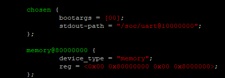
Modified device tree for test
Adding a simple, custom peripheral – The butter robot.
Now that we have a relatively good understanding of how a new peripheral can be added in QEMU and controlled via SW let us put that understanding into practice.
We will design a relatively simple memory-mapped peripheral device. The target is to make it appear in the system memory map and access it through C code. The simplest peripheral would be a static register set with pre-defined contents that we can read. This rather useless peripheral’s purpose is to ensure that our understanding of the system architecture is accurate. This will let us graduate into more complex peripherals in the future. Let us call this peripheral “The Butter Robot.”
The life purpose of this peripheral is to host a read-only register that pass (the characters) “BUTTER”
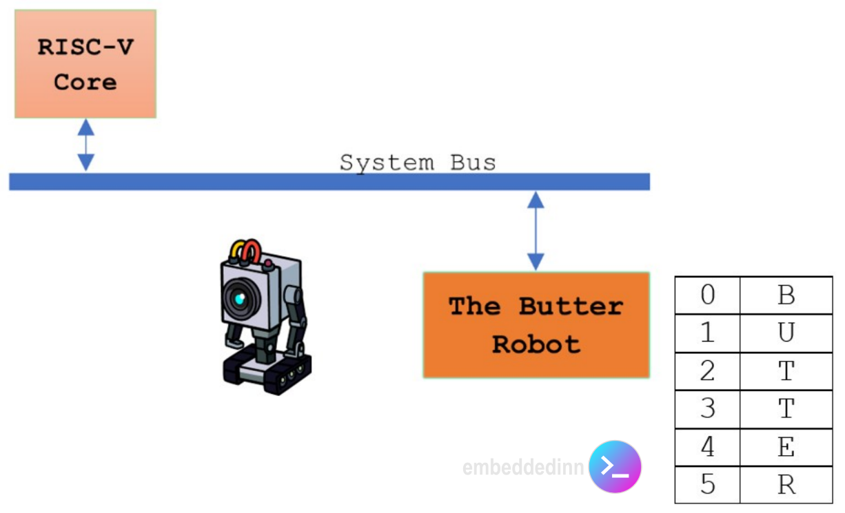
The butter robot system architecture
Here are the steps to follow to create the peripheral:
You can see the full diff of changes in my github QEMU fork.
-
Add a
butter_robotfolder underhw -
Make it visible to the build system by editing
hw/meson.build -
Create hw/butter_robot/Kconfig and include a symbol that can be used to control the inclusion of our peripheral into various machines.
- And include it in
hw/Kconfig
- And include it in
-
Create a build config for our peripheral in hw/butter_robot/meson.build and include the core files based on the Kconfig.
-
Now, build the core logic in
[hw/butter_robot/butter_robot.c](https://github.com/vppillai/qemu/blob/theButterRobot/hw/butter_robot/butter_robot.c)based on our understanding so far. -
Include
BUTTER_ROBOTinto theRISCV_VIRTmachine configuration in ` hw/riscv/Kconfig` -
Map butter robot into the system’s memory map. I used the location 0x50000000 with a 256-byte address space. This is defined in hw/riscv/virt.c
-
Instantiate the peripheral by calling br_create()
-
makeandmake installthe new machine.
I used the following code within the probe SDK we created before to test out the implementation.
#include <stdio.h>

int main(int argc, char **argv)
{
char *ptr = (char *)(void *)0x50000000; //BUTTER_ROBOT is mapped to this address in the RISCV_VIRT machine
printf("\n\nButter Robot is giving you: %.6s\n\n",ptr);
}
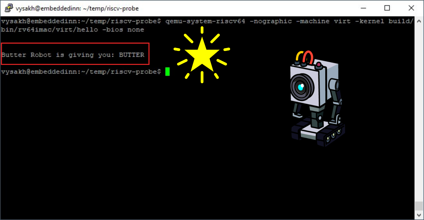
SUCCESS!!
Debug notes:
-
The min and max access size defined in the ops structure is critical.
- I left this at 4 and faced a bug that was very tricky to find. Finally, I executed QEMU with the
-d guest_errorsflag and it gave me the reason very clearly. Until then, I was just getting an unhandled trap error.
- I left this at 4 and faced a bug that was very tricky to find. Finally, I executed QEMU with the
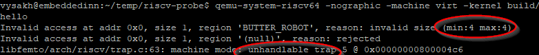
Exception trap debug


Leave a comment