

Building an E2E IoT system with Raspberry Pi
This article has been migrated from my original post at embeddedinn.wordpress.com.
Internet of things (IoT) is the future of embedded systems . Though it is nothing new (technically), it brings together advances in hardware engineering, software architecture, networking etc into a small package that makes our life easier and exciting. There are huge umber of articles throughout the internet that explains various aspects of IoT .
In this article/tutorial I will jot down one of my experiences with building an end to end IoT node.
The system
DISCLAIMER:
This system is not at all security focused. In fact, security has been disabled as much as possible.
I will not be going into the motivation I had to build this system . Through this article I am just sharing the experience I gained.
The end system has an embedded web-server hosted over an ad-hoc wi-fi mesh network that serves a 3D rendering of the orientation of the systems MU6050 6-access motion processing unit.
Though it is not a very utilitarian project, it presents huge learning opportunity.
Since there where too many unknowns for me to start with, I wanted to follow an agile development methodology for the system that will allow me to see a small working portion of the system at each point in time. Also, I wanted to use my brand new “Induino” to see how it flares.
Ultimately I ended up building a system which does this:
Now, on to how the components where build.
WebServer on Rpi
To get started, I wanted to build something that I had successfully build recently. So, as the first step, I brought up the Raspberry Pi with a minimalist kernel with lighttpd baked into the rootfs. If you are totally new to this, you can follow my tutorial here to get it done.
To include lighttpd in the final image, enable the following configuration in menuconfig:
Target packages -> Networking applications -> lighttpd [BR2_PACKAGE_LIGHTTPD =y]
There are two options to setup an IP address for the interface:
1) DHCP IP address
Run the following command to get an IP assigned to your interface from the router’s DHCP server.
udhcpc -i eth0
2) Static IP address
To setup a static IP address for your interface, add the following lines to /etc/network/interfaces. [Assuming that your router assigns IP in the 192.168.1.x range]
iface eth0 inet static
address 192.168.1.30
netmask 255.255.255.0
gateway 192.168.1.1
network 192.168.1.0
broadcast 192.168.1.255
I chose to go with a static IP since I will have to modify and use it to further setup my adhoc network.
To bring up the network with this IP, just issue the command ifup eth0and verify the IP with ifconfig eth0
Once my network is up, I was able to serve simple static webpages over Ethernet from the Pi from /var/www. I did the following changes to the lighttpd default config generated by buildroot to enable cgi modules for my second step – dynamic pages.
in /etc/lighttpd/modules.conf,
    add mod_cgi under server_modules
    uncomment include "conf.d/cgi.conf" in modules.conf

in /etc/lighttpd/conf.d/cgi.conf
    cgi.assign = ( ".sh" => "/bin/sh")

in /etc/lighttpd/lighttpd.conf
    add  ".sh" under static-file.exclude-extensions
NOTE:
Being a non-production, minimalist prototype, I decided to serve my dynamic pages and web-services from shell scripts as much as possible. Note that this is never advised for a production system or even a system that you are planning to do something beyond a temporary prototype.
Bringing up the PIs’ WiFi interface
Raspberry Pi doesn’t have an on-board WiFi interface . The easiest way to add WiFi capability to the Pi is to use one of those cheap USB WiFi adapters available in the market. I user a EDUP mini module which has a Ralink chip in it.
Official Raspbian image supports this module as plug and play. But with buildroot, we have to enable the required modules (only :smile: )
To enable kernel support for wireless networking and the Ralink chip, the following configuration has to be done. I enabled all these modules to be built into the kernel (as opposed to Modules) .
make linux-menuconfig
Netwoking support -> Wireless -> cfg80211 – wireless configuration API [CFG80211 =y]Netwoking support -> Wireless -> cfg80211 – wireless configuration API -> enable powersave by default [CFG80211_DEFAULT_PS =y]Netwoking support -> Wireless -> Generic IEEE 802.11 Networking Stack (mac80211) [MAC80211 =y]Netwoking support -> Wireless ->Minstrel[MAC80211_RC_MINSTREL =y]Netwoking support -> Wireless ->Minstrel->Minstrel 802.11n support [MAC80211_RC_MINSTREL_HT]Netwoking support -> Wireless ->Enable mac80211 mesh networking (pre-802.11s) support [MAC80211_MESH =y]Netwoking support -> Wireless ->Enable LED triggers [MAC80211_LEDS =y]Device Drivers -> Network device support -> Wireless LAN ->Ralink driver support [RT2X00 =y]And all devices under it [RT2800USB_RT33XX =y , RT2800USB_RT35XX =y, RT2800USB_RT3573 =y, RT2800USB_RT53XX =y, RT2800USB_RT55XX =y, RT2800USB_UNKNOWN =y]
make menuconfig
Target packages -> Hardware handling -> Firmware -> linux-firmware -> WiFi firmware -> Ralink rt27xx/rt28xx/rt30xx [BR2_PACKAGE_LINUX_FIRMWARE_RALINK_RT2XX =y]
This step is required since the Ralink module relies on the firmware to be loaded into the chip each time it is powered on. This step will download the .bin and copy it into /lib/firmware/ folder of the rootfs
Now we need the user space tools to connect to WiFi networks and check if our kernel support for the USB module is fine.
wpa supplicant and iw
The following configurations have to be enabled in the buildroot menuconfig
Target packages -> Networking applications ->iw [BR2_PACKAGE_IW =y]
Target packages -> Networking applications ->wpa supplicant [  BR2_PACKAGE_WPA_SUPPLICANT =y]
First off, let us try to connect to an existing WiFi network through wlan0 created by our USB “dongle”
To do this, first enter the network details in /etc/wpa_supplicant/wpa_supplicant.conf . A sample is given below:
update_config=1

network={
    ssid="my SSID"
    scan_ssid=1
    psk="Pass phrase"
}
scan_ssidis set to 1 to connect to hidden networks.
Now, run the wpa_supplicant tool to connect to the network (preferably run this in the background if you are not just testing if your configuration is fine)
wpa_supplicant -i wlan0 -dd -c /etc/wpa_supplicant/wpa_supplicant.conf
When you run this command, you should see the state change from GROUP_HANDSHAKE to COMPLETED in the prints. This means, a WiFi channel is established. Now you can run udhcpc comand (while wpa_supplicant is running in background) to get an IP (if dynamic IP is configured)
ad-hoc connection with iw
Once the WiFi interface is up, we can now setup the Ad-Hoc network.
The intention of setting up an AdHoc network is that when the final prototype is ready, the AdHoc network hosted by the Pi can be used as the initial configuration interface which allows us to setup the system parameters as required.
We use the user space tool iw to setup the interface mode to IBSS and then start a network . To do this automatically on each boot, we setup an init.d script at /etc/init.d - S90Adhoc as below. The S90 prefix is to wait for other init scripts that bring up other services (DHCP, dropbear etc) before the IBSS is setup (I know, not the best order :smile: ).
/etc/init.d - S90Adhoc
  #!/bin/sh
  echo "hello world - vysakhp"
  ifdown wlan0
  iw wlan0 set type ibss
  ifup wlan0 up
  iw wlan0 ibss join rpinet 2422
This will create an Ad-hoc network named rpinet in the 2422 channel that other devices like a laptop or ipad can join to.
However, at this stage, the devices joining the network wil have to setup a static IP address. This can be avoided by hosting a dhcp server in the Pi. Note that the Pi itself will need (?) to have a static IP
setting up the DHCP server
To enable the DHCP server in the Buildroot image for Raspberry PI, it has to be compiled with the following options enabled (in menuconfig)
- Target packages -> BusyBox -> Show packages that are also provided by busybox [ BR2_PACKAGE_BUSYBOX_SHOW_OTHERS =y]
- Target packages -> Networking applications -> dhcp [BR2_PACKAGE_DHCP =y]
- Target packages -> Networking applications -> dhcp -> dhcp server [BR2_PACKAGE_DHCP_SERVER =y]
- Target packages -> Networking applications -> dhcp -> Enable delayed ACK feature [BR2_PACKAGE_DHCP_SERVER_DELAYED_ACK =y]
S50–dhcp script under /etc/init.d will be as below. This will automatically start the dhcp server once the RPi is up.
Also, /etc/dhcp/dhcp.conf will look like:
ddns-update-style none;
option domain-name "example.org";
option domain-name-servers ns1.example.org, ns2.example.org;
default-lease-time 600;
max-lease-time 7200;
log-facility local7;
subnet 192.168.10.0 netmask 255.255.255.0 {
range 192.168.10.5 192.168.10.150; }
Once these configurations are done and the Pi rebooted, it will expose the rpinet AdHoc network to which any device can join. If you need to do an SSH login to the Pi over this network, dropbear can be used. To enable:
Target packages -> Networking applications -> dropbear [BR2_PACKAGE_DROPBEAR =y]
Induino and MPU6050
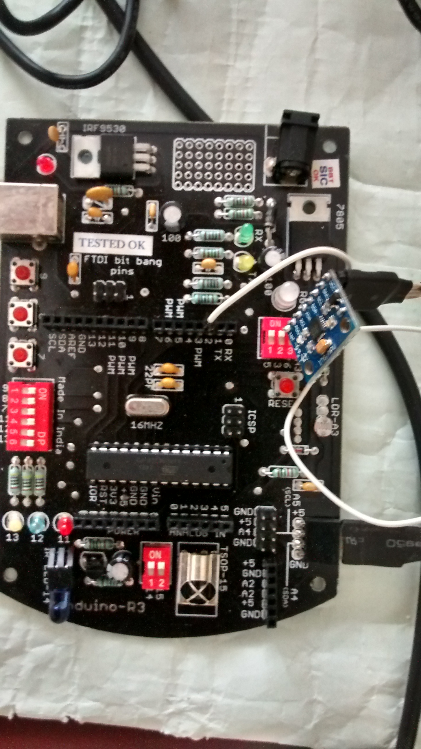
I purchased an Induino R3 instead of a an Arduino UNO since it has a lot of inbuilt peripherals that will help me with rapid prototyping. I bought the GY-521 MPU6050 module that comes with on-board voltage regulator from ebay. Jeff Rowberg’s i2cdevlib arduino library for MPU6050 comes with an example code on how to use the MPU and an excellent processing “teapot demo” similar to the one supplied by Invensense.
To get started, I soldered the berg strips to the GY-521 module, hooked it up with the Induino and loaded the sample sketch that came with Jeff’s library with OUTPUT_TEAPOT enabled.
Then I ran the teapot demo in processing (after installing toxic libs for processing and tweaking the code to use my serial port) . The result was inspiring :smile:
ThreeJs
Being totally new to threejs, I wanted to first see how the whole thing works. To begin with, I followed the tutorial here and ironed out the setup issues . Since I did not want to compromise the integrity of my setup, I hosted the sample page in my local Apache2 setup. Firefox Firebug came in extremely handy to sort out the initial issues.
I had just a conceptual understanding of websockets at this point. So, I wanted to use it get the values from Induino into the webpage in real time so that I will get a practical understanding of what websockets are.
However, as I mentioned in the beginning I wanted to follow an Agile methodology that allows me to see a working piece of the system at each milestone. So I decided to first get the threejs part of the simulation working. For this, I captured the quaternion values that the Induino spits out and stored it as a Javascript . These where then used to rotate a plane box that was created using threeJs methods.
The sample with a small sample set is given below:
Serial Port
I enabled support for the FTDI232 chip in my Induino R3 in the kernel configuration at :
Device Drivers -> USB support -> USB Serial Converter support -> USB FTDI Single Port Serial Driver [USB_SERIAL_FTDI_SIO = y]
Once the Induino is connected, the serial port device [/dev/ttyUSB0 in my case] needs to be configured to start reading from it. I used the following stty command.
stty -F /dev/ttyS0 cs7 cstopb -ixon raw speed 115200
Once configured, quaternion values coming form the MPU can be read from /dev/ttyUSB0 as if being read from a regular file. The use of this can be seen in the next section where I am discussing my websocket server.
WebSockets
A websocket is a beautiful mechanism that allows you to have a near-real time, duplex communication between a server and webpage . All modern browsers support it and the data can be readily used in javascript.
Since my target system is a minimalist RPi based embedded system, I did not want to go with full fledged socket server implementations. Moreover, I wanted to learn how these cuties are build.
At first, I glaced through the documentation available on socketservers and found this MDN article to be very straight forward and useful. I also looked into this beautifully written shell script websocket server to get an understanding of how to setup my own server. The coproc redirect was particularly interesting in his script.
After getting a hang of how websockets work, I went ahead and wrote my own websocket server (adapting portions from Krey’s script). Since my data is always smaller than 127 bits (7 bits limit used to denote length in RFC6455 base framing protocol ), my header is more or less hard-coded. Initial glitches where ironed out using wireshark to trace the local loop-back traffic using its support to parse websocket traffic.
Note: I marked my packets as “text frame” in the header. This needs the data to be terminating with \r\n . [increment length field by 2]
Finaly, my Websocket Server code looks like this:
Bringing the pieces together
I modified my sample code to move a threeJs plane with the quaternion data dump as below and copied it to its final resting place /var/www of RPi root and started my websocket server .
Final webSocket code:
Final HTML:
the end result — geekNirvana


Leave a comment