

USB-2.0
This article has been migrated from my original post at embeddedinn.wordpress.com.
Universal Serial Bus is a host-centric, 4 wire bus protocol targeting a standard, low cost interface with self-identifying, dynamically attaching peripherals that automatically map functions to drivers and configurations and low protocol overhead and guaranteed bandwidth and low latencies for demanding applications like telephony, audio, video etc.
The USB specification was jointly developed by a conglomerate of which the major players included HP, Intel, LSI, Microsoft, Renesas and ST-Erricson. The specification and certifications are maintained by the USB implementer’s Forum (USBIF)
History of revisions

Revision 1.0 (January 15, 1996)
- Low-speed transfer rate of 1.5 Mbits/s
- Full-speed transfer rate of 12 Mbits/s.
Revision 1.1 (September 23, 1998)
- Improved specification and was the first widely used version of USB.
Revision 2.0 (April 27, 2000)
- High-speed transfer rate of 480 Mbits/s.
Revision 3.0 (November 17, 2008)
- Super Speed USB (Raw data throughput up to 5.0 Gbit/s)
Through this article we will be concentrating on the high speed USB protocol revision , popularly called USB 2.0.
The Basics
Bus Topology
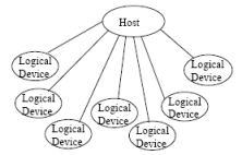
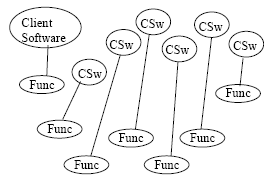
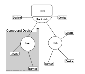
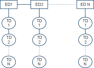
Basic USB follows a tier Star Topology as shown in the below figure.
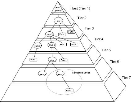
The Host is at the top of the tier and all “functions” connect to the host ultimately. A “hub” is required to expand the connectivity of the “root-hub” which is the ultimate terminating point in the host. A hub is the center of each tier and each tier has a star topology centered at the hub.

There are limitations set to the maximum delay that can be induced by each element of the USB protocol. As a result, the net “turnaround time” restricts the number of tiers to be 7 – including the top (root/host). A function which contains a hub and a function together is called a “composite device”. The 7th tier is not supposed to contain a hub since no further levels are allowed.
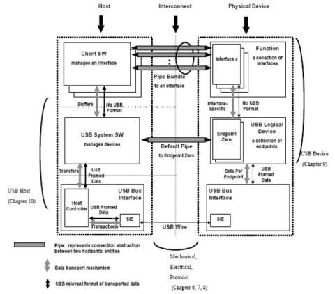
System Components
The USB system is defined in terms of 3 major areas. This includes the USB device, the USB host and the USB interconnect.
A USB device can either be a hub which provide additional attachment points to the USB or functions which provide additional capabilities to the system.
There is only one host in any USB system . The USB interface to the host computer system is called the host controller. The host controller may be implemented in hardware, firmware or software. A root hub is integrated within the host system to provide one or more attachment points.
The USB interconnect is the physical interface of the bus and is described by the electrical and mechanical specification of the bus.
The USB interconnect and Signalling
Interconnect
The USB achieves specified protocol speeds over copper using a 4 wire physical interface. The bus also supplies power to the devices .
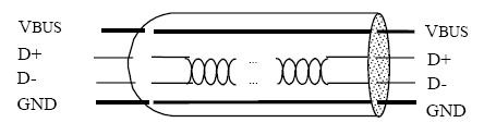
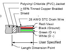
Maximum length of the cable is defined in terms of the signal latency and signal integrity . A standardcable conforms to the color coding as shown in the figure
Signalling
USB protocol follows differential signalling in the D+ and D- lines of the cable. Data is encoded using NRZI protocol and is represented in terms of J (where current is driven into the D+ line) and K (where current is driven into the D- line)
In NRZI encoding, a stream of 0s is represented by J-K toggle every bit time whereas a stream of 1s maintains the previous state of the D+ and D- lines. A single ended zero (SE0) is signalled by driving both D+ and D- lines
Synchronization between the host and the device is maintained by a digital phase locked loop (DPLL) at both ends. However, a long stream on 1s will cause the DPLL to lose sync and hence, a zero is “stuffed” after every set of 6 consecutive 1s. This is called bit stuffing.
“Bit times” are determined by the speed mode in which the function is operating. For example, a device operating at low speed has a data rate of 1.5Mbps. Thus one bit time will be (1/1.5 us).
Speed modes are differentiated by the terminating resistors in the D+ and D- lines.
For a Low speed the D- line will terminate in 1.5K ohm pull-up resistor whereas a full/high speed device will have a similar pull-up in the D+ line. Thus, initially a high speed device acts as a full speed device . The device generates a “high speed chirp” which is a set of 15 J-K pairs to indicate to the host that it is a high speed device. (480Mb/s)
Once the speed mode is detected, the host begins the “enumeration” process, which is nothing but configuring the function for use. But, before going to the details of enumeration, we need to understand certain basic terminologies. This is explained in the next section.
Protocol Basics
Basic Terminology
- Signalling mode
One of the speed modes- Low Speed : 1.5Mb/s
- Full speed : 12Mb/s
- High speed : 480Mb/s
-
Host
The computer system (which can also be an embedded system) to which the usb device is connected. The host initiates all communication and is the master of the bus. There will be only one USB host in a bus topology. -
Device
The usb function which is connected to the host. A device may contain multiple functionalities which may or may not be available together. This is discussed in detail in later sections. -
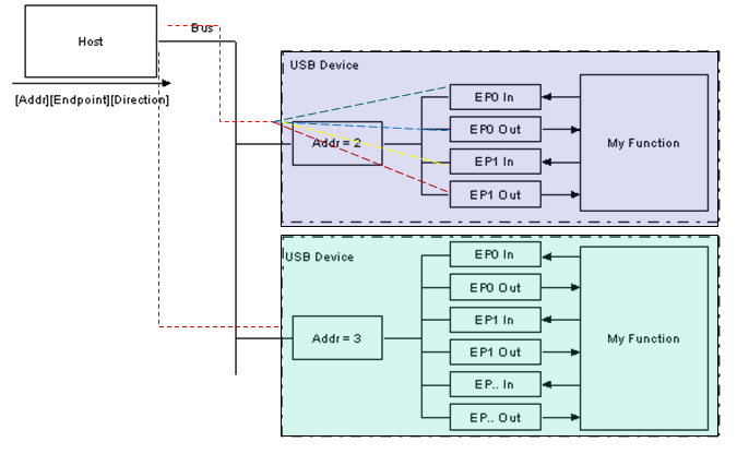
Device Address
A unique 7 bit address assigned to the device by the host when it is attached. This address is used by the host to direct all communication to the desired device. A device when connected initially to the host, will have address 0 (default address). -
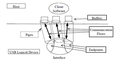
End Point
An endpoint is the most granular classification in a device to which the host can communicate. An endpoint is usually implemented as a buffer to which host sends data (protocol specific or not).Every USB device should have the default Endpoint 0 (EP0) which is used by the host to identify the capabilities of the device and send configuration information to.
There can be a maximum of 31 endpoints including EP0. All endpoints except EP0 are unidirectional and each endpoint is identified with a unique 4 bit endpoint number and its direction.Endpoint direction is denoted in the lower nibble of the 8 bit endpoint address .Thus EP1 IN will be addressed as 0x10 and EP1 out will be addressed as 0x18.
-
Pipe
A logical connection between a point in the host and a point in the device. A device can have maximum of 31 pipes including the default pipe terminating at EP0.USB pipes are classified in two as unidirectional stream pipes which can carry data in any format and stream pipes which can carry data with no specified formats.
The default pipe terminating at EP0 is always a message pipe and the pipes to other endpoints are all stream pipes.
-
Interface and configuration
Interface and configuration are two levels of hierarchical arrangement of the capabilities within a function. A function (device) may have multiple configurations and multiple interfaces associated to each configuration. Each Interface may have multiple endpoints associated with it. At any given point of time, only one configuration can be loaded by the host. The interfaces group the endpoints logically and makes it easier to load the device drivers.The host reads out capabilities of the device in terms of the configurations and interfaces with the device descriptor, interface descriptor and endpoint descriptor. these are pieces of information passed on to the host when it issues certain standard commands to the device .
A specific interface/configuration can be loaded or unloaded by the host during device operation.

-
Device Class
The USB devices are classified into different classes so as to make driver development and classification easier. However, there is no directive that a device must fall into a class specification. A certified device can still be using completely proprietary drivers . however, the device must confirm to basic protocol specified behavior as specified in Chapter 9 of the SUB 2.0 specification along with electrical and mechanical compatibility. -
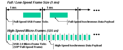
Frame
The entire communication happening in the USB bus , irrespective of the target device, happens in segments divided into frames. For a low/full speed device, a frame is 1ms wide where as a high speed device has a frame width of 125 us. Each frame is distinguished by a 11 bit frame number which is issued as a special packet called Start of Frame (SOF). Within the frame there can be multiple packets of data indented to be delivered to different devices. The actual packet delivery is explained in following sections.
-
Stall
When an endpoint is not ready to send or receive data, the endpoint sends a NAK. Where as if the endpoint receives a wrong command or is no longer able to respond because of some internal error, then the device sends a STALL handshake. Upon receiving a STALL handshake, the host has to take corrective measure to restore the functionality in the endpoint. -
Timeout
A high speed device connected to the last tier (7th tier) of the topology can take up to a maximum of 736 bit times to respond to any of the host requests. If no signal is seen within 816 bit times, the host will timeout. Following a timeout, the host will issue a reset and try to re-enumerate the device.
USB Basic Communication Flow
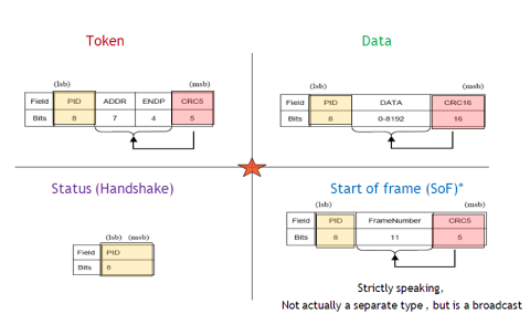
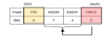
All data communication in the USB bus happens as packets. A communication is initiated by the host by issuing a token packet addressed to the device and endpoint to which the following packets are indented . The token packet contains an 8bit packet identification (PID) that defies the type of transaction that is about to happen
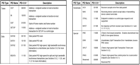
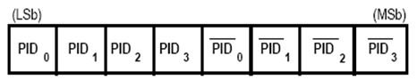
The PID is actually of 4 bits width. The lower nibble is compliment of the higher nibble to provide a sanity check.
Following a token packet is a corresponding data packet in the direction mentioned in the token packet. This is an optional stage for different types of tokens and are described in the corresponding places in this document.
Once the transaction happens, it is given a handshake packet.
A start of frame (SoF) packet is broadcasted by the host every millisecond (in case od LS of FS devices) or every 125us (for HS devices).
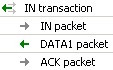
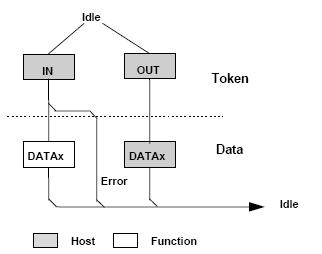
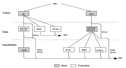
Thus every transfer contain multiple transactions. Each transaction has three stages
- A token stage: where the host issues a token packet addressed to the device to which further communication is going to happen. It also indicates the direction of transfer.
- A Data Stage: where the actual data transfer happens through a data packet
- A status stage: where the data transfer is acknowledged with a handshake.
Enumeration
The process of identification of the capabilities of a USB device and mapping it top the corresponding drivers in the host system is the process of “Enumeration” . Once a device is enumerated the Host will be aware of the speed mode, available number of endpoints and their properties and classes etc. The steps are as described below.
Here we are assuming just one device plugged directly into the root hub of the host.
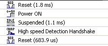
- As soon as the device is plugged into the hub port, there will be a bus reset with a SE0 (D+ and D- low) followed by power up of the bus.
- This is followed by speed mode detection of the device using the data line pull-up
- A low speed device will have a 1.5 K Ohm resistor connected to its D- line where as a full/high speed device will have it connected to the D+ line.
- A high speed device starts its operation as a full speed device. Once the host resets the bus , the device sends a low frequency chirp (16 J-K pairs) to indicate to the host that the deice is capable of high speed operation. This is acknowledged by the host with a reverse chirp.
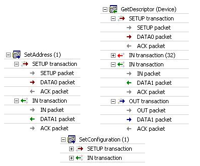
- Once the speed mode is detected, the host issues a “standard request” termed ‘GetDescriptor (device)’ to EP0 to read out the capabilities of the connected device.
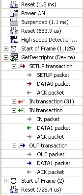
- Reading the descriptor happens in multiple levels since descriptors are differentiated hierarchically depending on the type of information they convey as explained in the previous section.
- After reading the device descriptor for the first time, if the device can be supported by the host (decided by various factors), the bus is reset again and the device is provided a unique 7 bit address.
- After getting the device to the addressed state, further details of the device are read out via other descriptors as shown in the following figure
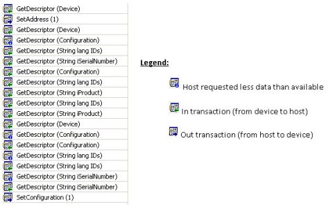
- The set configuration comand is used once all available configurations of the device is read out. The comand uses an index to set which configuration of the device is to selected.
- Once a configuration is set, the corresponding class driver (more on classes later) will be loaded and class spec
Once the device is enumerated and the endpoints are configured, the logical communication arrangement is as shown in the figure below.
The system software is primarily the root hub driver that keeps track of all the devices connected to it. Any configuration related communication happens via the default pipe to EP0.
Drivers specific to the endpoints can communicate via the corresponding pipes.
Transfer Modes
A usb device can contain multiple endpoints as discussed earlier. Each endpoint can be an IN or OUT endpoint depending on the direction of data transfer, Another parallel classification is based on the type of data transfer happening in the endpoint.
The four types of transactions that happens in the USB bus are
- Control Transfer
- Bulk Transfer
- Isochronous transfer
- Interrupt Transfer
During enumeration , each endpoint that will be active for teh selected configuration will be classified to have one of the four transfer types.
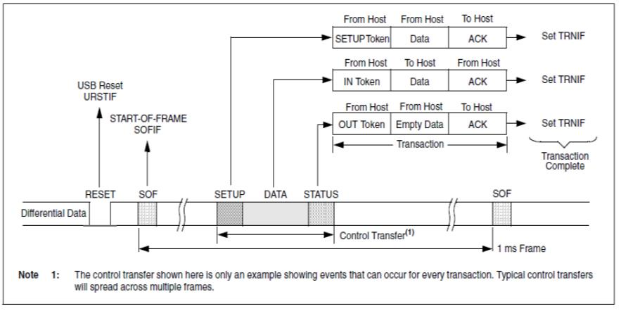
Control Transfer
Control transfer is used for communication between the host and EP0 function (device) . Examples include the chapter 9 command transactions like SetAddress, Getdescriptor, SetDescriptor etc.
A control transfer happens in three stages namely
- setup stage
- data stage
- handshake stage
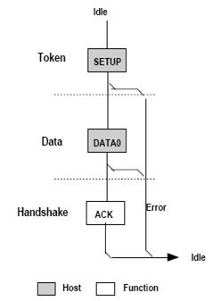
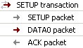
The setup stage starts with a setup token issued by the host followed by a data packet which contains the actual command information which is in turn followed by the acknowledgement stage.
The data stage is optional This is followed by an optional data stage depending on the type of command issued. for example, the set configuration command has the index of the configuration to be set embedded into the command. thus no separate data stage is required in its case whereas the Getdescriptor command requires multiple data stages to transfer all required information.
Even when multiple devices are connected to the host, control transfer is always assured 10% of the bus bandwidth. i.e 10% of the time in a time in a 1ms (20% of the 125us micro frame in case of HS devices) will be always reserved for control transfers.This is because if there are some data errors in the otehr endpoints, control transfers are use to perform corrective action on those functions.
Isochronous Transfer
This data transfer mode where where there is guaranteed access to the USB bus bandwidth.
Bus Bandwidth
The USB communication happens in the form of frames. Each frame can contain transfers indented for multiple devices. Bandwidth specifies the amount of time in a 1ms / 125us frame that is dedicated to a particular device. This can translate to the amount of data when we consider the speed mode (1.5/12/480 Mb/s)
Interrupt Transfer
Interrupt transfer provides a mechanism to have an ensured communication between the device and the host in periodic intervals of time.
When an interrupt endpoint is enumerated , it can specify a polling interval ranging between once every frame to once every 255th frame.
In case if the device do not have data to transferred when polled, the next retry will only be in the next service frame.
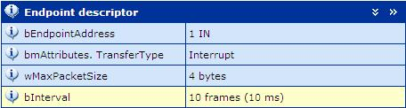
Maximum data packet size is 8 bytes (LS), 64 bytes (FS) or 1024 bytes (HS) per transaction.
The figure below shows the endpoint descriptor for the interrupt endpoint of an optical mouse and periodic polling of the endpoint.
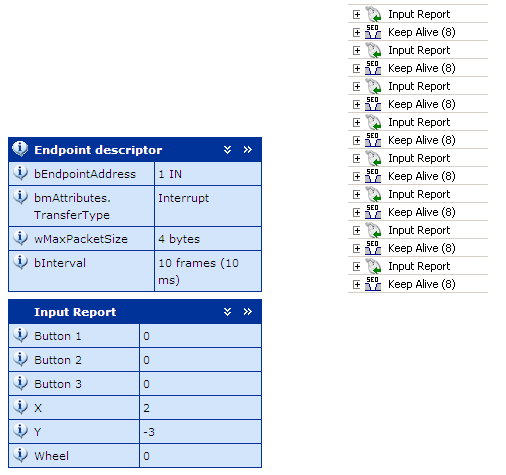
Note on Keep Alive:
All hub ports to which low-speed devices are connected must generate a low-speed keep-alive strobe, generated at the beginning of the frame, which consists of a valid low-speed EOP. The strobe must be generated at least once in each frame in which an SOF is received. This strobe is used to prevent low-speed devices from suspending if there is no other low-speed traffic on the bus.
Bulk Transfers
Bulk transfers are used when large amounts of non-time critical data is to be transferred between the endpoint and the host. Examples of devices utilizing bulk data transfer mechanism include flash drives (mass storage class devices), printers , scanners etc. The reliability of data content is more important than data rate for these devices. Thus, bandwidth available for bulk transfers can vary from frame to frame depending on the configurations of other devices connected to the host.
USB Reliability
Errors
There can be errors occurring in the USB bus communication due to various reasons. This section gives a brief overview of the common errors and the corresponding recovery mechanism implemented by the USB framework.
Error types
-
PID Errors
The 8 bit PID is actually constructed out of a 4 bit PID and a 4 bit PID compliment as shown in the figure below. If there is a mismatch , the device should not respond and a timeout will happen at the host side (ref: section 8.3.1of USB 2.0 spec).Full decoding of the PID is mandatory frame all the devices .
-
CRC Error
Fields following the PID are used to compute a cyclic redundant code which is used to validate the sanity of the received data. Any data with corrupt CRC will be responded with a NAK.CRC is 5 bits for a token packet and SOF whereas it is 16 bit for a data packet. There is no CRC for handshake packet.
- Invalid command
Whenever an endpoint receive a “intact but logically wrong” packet like a wrong command, or if something goes wrong within the device which makes the endpoint un-usable, the endpoint stops functioning and any requests addressed to the endpoint is gives a STALL handshake as response
Error handling
-
NAK
Whenever the host receives a NAK from the device retries are triggered at the hardware level for the first 3 times. Beyond this, there will be software intervention. -
STALL
When an endpoint STALLs, the host has to send a ClearFeature command with the ‘feature selector value’ addressing the interface to be cleared . This is sent to the control endpoint (EP0) . Thus even if an endpoint stops functioning, a ClearFeature is applied to all endpoints under that interface. -
Timeout
When no signals from the device reaches the host for a specified interval of time , the host resets the device by applying a reset signal (driving SE0 for more than 2.5us on the data lines)
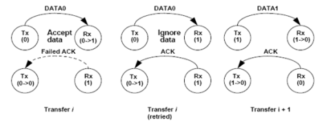
Data toggling for synchronization
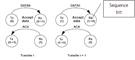
USB employs a simple mechanism known as data toggling to ensure synchronization of data transferred between the host and the devices.
While doing data transfers, the host uses two types of data tokens namely Data0 and Data1. Initial data transfer will be done using the Data0 token. Upon getting an ACK from the device, the next piece of data is sent using Data1 token. The device also maintains a sequence bit which is toggled upon successfully ACKing the transfer.
However, in case there is some problem and the data is not accepted (NAK sent), then the host and device maintains the sequence bit status and the immediate next transfer happens with the previous data token type
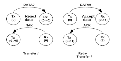
Suppose an ACK is missed in the bus and not received at the host, then the host re-sends the data with same token (DATA0). however, at the device side, the sequence bit is already toggled as a result of the previous transaction. So the device ignores the received data and sends an ACK.
USB Classes
After enumeration , the actual communication to the device is initiated by a driver software within the host which knows the behavior of the device. USB protocol is very versatile to use existing drivers along with the new drivers so that USB can act solely as an interface or communication medium. This is implemented using a filter type driver hierarchy by dividing the USB devices into classes.
We will try to understand the concept of USB Classes by considering the well known example of a Mass Storage Device aka USB Flash drive.
A USB flash drive primarily had a mass storage memory and memory controller attached to a USB controller.
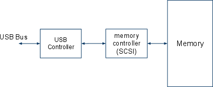
A typical USB flash drive will have a memory controller interface that follows the SCSI protocol which is yet another protocol like USB which is used to have entire control of the memory at the logical block address level. Thus, after enumeration the device (flash drive) has the role of a slave to respond to the SCSI commands that are issued by the host.
SCSI has 3 stages for every transaction namely
- Command stage
- Data Stage
- Status Stage
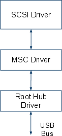
The file table and all logical memory handling is done by the SCSI driver that resides in the host.
Now, the SCSI driver is a generic driver that has no relation what so ever to USB protocol. USB being a bus protocol acts as a medium to transfer SCSI protocol data units between the host and device. This is enabled by identifying the device as a Mass Storage Class device (MSC device) at an interface level. Once a device is identified to have a MSC interface, a MSC driver stack is loaded by the host. Any communication happening to or from the interface specified as MSC interface will be initiated by the MSC driver by placing a request to the root hub driver . The root hub driver (RHD) collates multiple requests from different drivers and forms the frames.
Major part of the MSC interface driver, is a wrapper to the actual SCSI driver. The SCSI driver will place requests to the MSC driver which is in turn transmitted over USB by the root hub driver (RHD). However, the SCSI driver need not have any awareness of the USB protocol or structure. It can call the MSC driver APIs which will in turn place a request to the RHD. On the other hand, the RHD need not know any implementation details specific to SCSI or MSC.
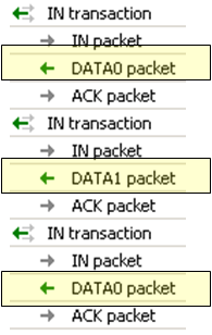
The figures below illustrate clearly as to how the SCSI commands are embedded into the USB transfers
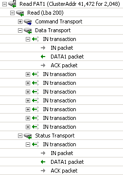
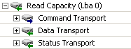
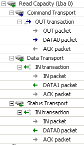
Thus the class based architecture enables a USB device to be controlled by an existing driver whose implementation is independent of USB protocol (reuse of existing drivers)
Host Scheduling
So far we have been concentrating on a single device being connected to the Root Hub . However, the protocol is designed to handle up to 126 devices connected in a tiered star topology. In this section , we will discuss how the host schedules transactions to multiple devices of varying speed modes connected to it at the same time
As seen from the topology, the devices are connected to a single point in the root hub via port expansion units called hubs. A hub has an up stream port connecting towards the host and a downstream port which actually provides the connection points to the devices.
Thus hubs play a major role in the topology of USB bus by taking up some of the ‘duties’ of the host like sending frequent ‘keep alive’ signals. Discussing the hub protocol is outside the scope of this tutorial.
Once multiple devices are connected to the topology, the host gives each of them a unique 7 bit address, for this the initial communication happens with device address 0 (the default address of a device before getting the actual device address.) preventing device addressing at address0 is collaborated between the host and the hubs.
Once addressed, the actual enumeration of the devices happens by which the host reads out the ‘capabilities’ and ‘requirements’ of the devices in terms of the descriptors as described in pervious sections.
If a device requests for more resources than that available with the host, the device will not be enumerated. To elaborate this use-case, consider the scenario where there are three isochronous endpoints (functions) that are already enumerated which consume all the available bandwidth. When a newly attached device requests for some bandwidth that is not available (since it is pre-occupied by devices that are already enumerated), then the device will not be enumerated by the host.
Once devices are enumerated, the host creates its internal data structures based on the type of endpoints and the requests received from the client software. This is explained in brief below.
Once a device is enumerated there will be a endpoint data descriptor generated for the device at the host. This could be considered as the head node of the linked list holding the data to be transferred to the specific device endpoint. Attached to it will be the transfer descriptors which hold data to be send to the endpoints. Data coming as part of the Client software (device drivers) requests will be attached as transfer descriptors.
Transfer scheduling to multiple endpoints is done in terms of frame number. For example, an interrupt endpoint can requests to be polled every 10th frame, then the host will schedule to send the corresponding transfer descriptor every 10th frame. As for the example shown in figure the transfer descriptor can contain an IN token.
Many of the images are taken from sample traces provided by Ellisys USB analyser tool and the USB 2.0 Specification itself.


Leave a comment