

USB-3.0
This article has been migrated from my original post at embeddedinn.wordpress.com.
Note: The target audience for this a tutorial are people who are aware of the USB 2.0 Architecture. If you are new to this, please go through my tutorial on USB 2.0 (here) first.
There are numerous articles in the internet that gives a peripheral understanding of this technology. However, this article is all about the core concepts and building blocks of USB 3.0
1. Introduction
Universal Serial Bus is a part of our day to day life. The number of USB compliant devices is growing day by day. And now, we have a relatively new protocol that is meant to be backward compatible to USB 2.0 and at the same time be faster and more efficient. Let us take a look into what makes up this USB super speed (SS) technology. This article assumes that the reader is aware of the USB 2.0 Protocol.
Most of the diagrams are taken from USB 3.0 specification document. Screenshots from sample traces included in Ellisys SuperSpeed USB Explorer 280 software are also used.
2. USB 3.0 Design goals
USB 2.0 is a very popular and dominant technology. Even by sheer numbers, it would be unwise to think of a technology to replace it altogether. The key to change would be to come up with a technology that is backward compatible yet better that USB 2.0. This is the basic philosophy behind the USB 3.0 protocol. The design Goals can be summarized as below
- Preserve the USB 2.0 model of a smart host and simple device
- Improve power management
- Preserve investment – backward compatibility
3. Architectural overview
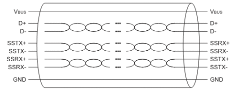
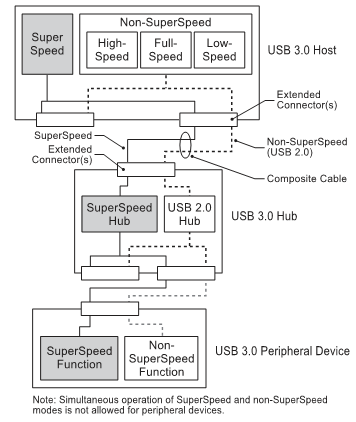
This section discusses about the key architectural components of the USB 3.0 protocol. To start with, the model of a smart host and simple devices as in USB 2.0 is preserved. However, the enhancement is a dual bus with dedicated physical channels for Tx and Rx. There is an additional pair for the backward compatibility (USB 2.0 Traffic). This new USB cable with 3 twisted pairs of data lines and a power line pair is called the composite cable.
USB 3.0 inherits most of the core architectural elements from the previous version. It maintains the following with minor mortifications
- Single host Tired Star Topology
- Transaction types : Control, bulk, isochronous and interrupt
- Concept of functions, endpoints, pipes etc.
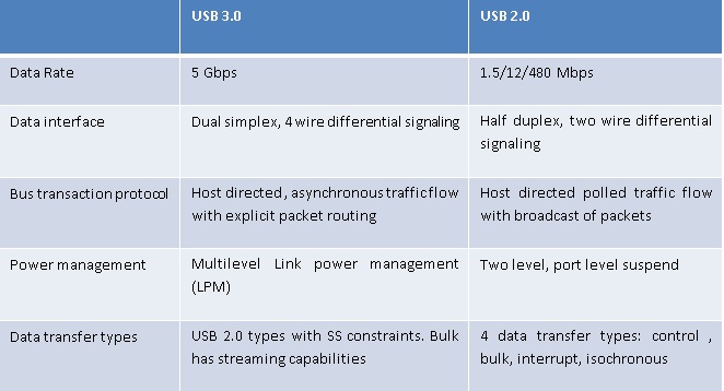
However, there are some key differences. They are tabulated below
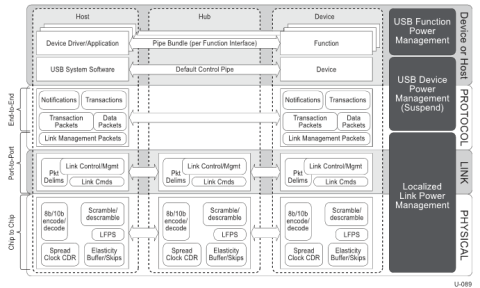
The USB 3.0 protocol is a layered protocol as shown in the figure below. The key features of each layer is described below
3.1 Physical Layer
The Key functions of this layer include
- Enables chip to chip communication of protocol data with minimal processing
- Detection and presentation of speed modes
- Ensure seamless high performance communication
The functional modules include
- 8b/10b data encoding
- Data scrambling
- Low Frequency periodic signaling
- Spread Spectrum Clocking and elastic buffers
3.2 Link Layer
Physical connection between two USB 3.0 ports is called a link and the link layer maintains this physical connections. Functions include
- State machines to maintain the physical connections
- Port to port reliability management
- Buffering of data and protocol layer information elements
- Packet framing
- Error checking of header packets
3.3 Protocol Layer
The protocol layer defines the end to end communication between the device and the host. Packet headers are the building blocks of the protocol layer. They are used to route data to relevant ports only.
Now, let us look into the detailed implementation of each layer
4. Physical Layer
The PHY layer maintains data integrity and enables reliable communication of high speed data through the link by using number of techniques. The key techniques used are described below.
4.1 8b/10 Encoding
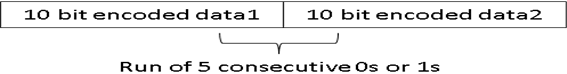
USB 3.0 uses ANSI standard (X3.230-1994/INCITS 230-1994), commonly known as 8b/10b encoding for medium encoding. This technique is used to maintain a balance in the number of 0s and 1s being transmitted over the medium. The standard encoding ensures a difference of less than 2 in a set of 20 bits that are transmitted in the medium. The standard encoding is slightly altered to ensure that there are not more than 5 1s or 0s in a row so that the DPLL remains locked.
Basics of the 8b/10b encoding are given below.
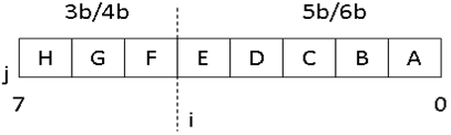
An byte of data is split into two groups of 5 and 3 bits and are called the 5b/6b and 3b/4b group respectively. Additional bits i and j are added to the groups respectively thus making the encoded data *ABCDEiFGHj* **. The bits i and j are selected from a lookup table specified in Appendix A of the USB 3.0 specification
The 8b/10b encoding maps a set of 256 elements (28) into a set of 1024 elements (28+2). Some symbols that have continuous run of more than 5 1s or 0s are ignored. The remaining is divided into two sets namely
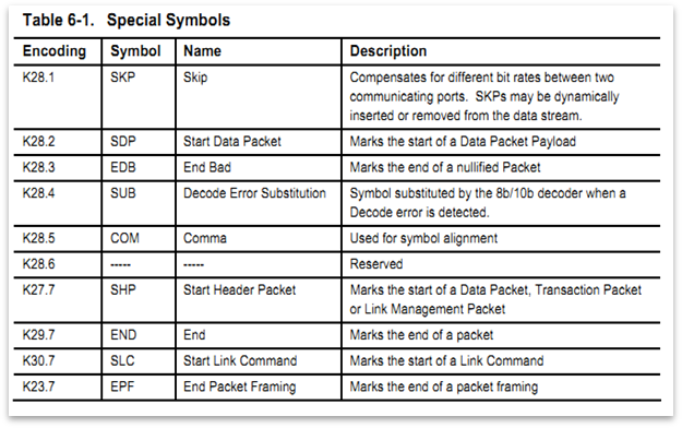
- K codes : used as special symbols for data framing and link management
- D codes : used for actual data encoding
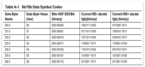
The original data bits (un-encoded) are represents as D.x.y where x ranges from 0-31 (5b/6b group) and y ranges from 0-7 (3b/4b group). The lookup table has two sets of entries named the D.x.n and D.n.y. The correct encoding for the data is selected by the PHY layer from the lookup table.
In the case of a “running disparity” where there is a run of 5 consecutive 1s or 0s when two pieces of data are kept together after encoding, an alternate encoding is to be chosen from the table. (hence the RD+ and RD- entries)
Special symbols (reserved symbols) follow a different encoding represented as K.x.y. Any unknown symbol is replaced with K.28.4 and is passed on to the link layer for further processing.
4.2 Data Scrambling
Data scrambling is a technique used to reduce inter signal interference by spreading the power spectral density of the data being transmitted in the links. Data scrambling is implemented prior to 8b/10b encoding by serially XOR-ing the data with output of an LFSR. Training Sequence codes and K codes are never scrambled. The LFSR is synchronized by re initialization with K.28.5 (COM)

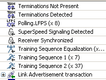
4.3 link initialization and training
One of the first operations that take place once a USB 3.0 compliant device is plugged into the host/hub is link initialization and training. These operations sync the link operators in terms of the operating parameters and make them ready for actual data transfer. The key player in Link initialization and training is an “ordered set” which is a predefined sequence of D and K values. The key functions of this operation include
- Configuration and initialization of the link
- Bit and Symbol locking
- Rx Equalization
- Lane polarity inversion
4.3.1 Clock Locking
The clock and data recovery circuit (CDR) extracts the phase and frequency information of the link attached to. For this, long sequence of D.10.2 symbols are used since this symbol have alternating 1s and 0s
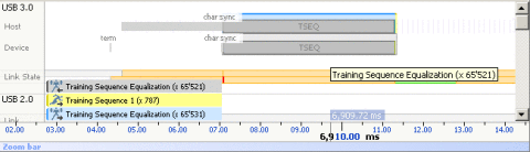
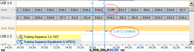
4.3.2 Data Locking
The start and end of every 10 bit symbol is demarcated by a COM symbol (K.28.5, comma). The symbol is unique and will not be found in any other combination of data being transmitted in the link. This symbol is used by the clock and data recovery circuit to get a data lock on the link.
The figures below shows a training sequence and the COM symbol embedded on to it.
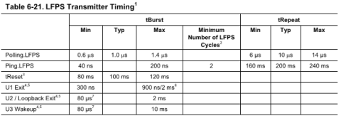
4.4 Low Frequency Periodic Signaling (LFPS)
LFPS is a sideband communication mechanism for low level interaction between the link partners in low power states or during a training sequence. The purpose of the low frequency signal is determined based on the burst timing
4.5 Spread Spectrum Clocking
The super speed USB architecture supports the use of separate clock reference drivers at the two link partners. However, the accuracy should be ±300 ppm. However, the clocks are not generated in the common square wave pattern but are rather in a spread spectrum pattern with ±5000 ppm accuracy. This is because a fixed frequency square wave has power dissipation in a narrow peak in the power spectra which will make the device non compliant to FCCI EMI regulations. However, when the clocks are generated in a spread spectrum, the power dissipation peaks also spread out in the spectra.
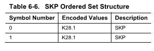
The variation in frequency of the Tx and Rx ends are compensated by injecting extra data at the transmitter. An average of 1 symbol per 354 symbols is injected in this manner. This extra data insertion/absorption is facilitated by “elastic buffers”. The transmitter allows to buffer up to four SKP ordered sets in the elastic buffers to facilitate frequency delta compensation.
5. Link Layer
The USB 3.0 link layer is responsible for maintaining the link level interaction and state machines. It also handles link power management, packet framing and link errors. A link can have the following states.
- U0 : The normal functional states
- U1 : Low power state with no packet transmission
- U2 : More power efficient state with increased exit latency
- U3 : Suspended state
- Recovery : State waiting for host reset. Needs retraining
5.1 Packets and packet framing
Packet headers constitute the basic building units of the link management protocol. They are used to determine what to do with the data received and also to maintain link states. Each header packet is 20 symbols long (20 bytes decoded). The 4 data packet headers are
- Data Packet Header
- Link Management Packets
- Transaction Packets
- Isochronous time Stamp Packets
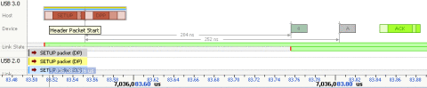
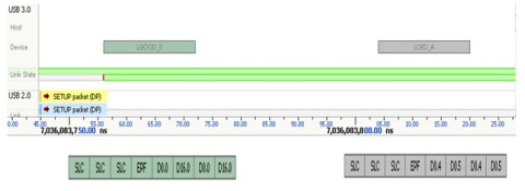
The figure shows a setup transaction with a header followed by data

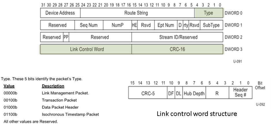
5.1.1 Header packets and framing
All header packets have the following common fields
- Header packet start ordered set (HPSTART) made up of 3 start header packet symbols (K.27.7 – SHP) and 1 end packet framing symbol (K.23.7 – EPF)
- 2 byte CRC16 computed on the 12 byte header information
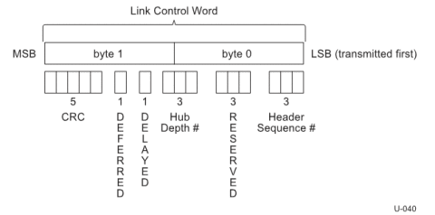
- 2 byte link control word
The 12 bytes of information determine the purpose if the header packet.
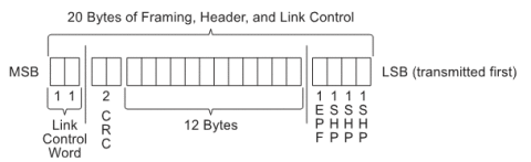
The link control word (2 bytes MSB) facilitates link level and end to end flow control. In includes the information required to route the packet to only the desires link in the tired star topology. This prevents broadcast of data and enhances power utilization. Only the ITP will be broadcast in USB 3.0
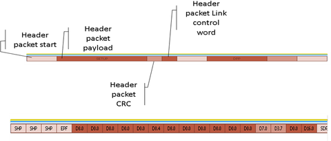
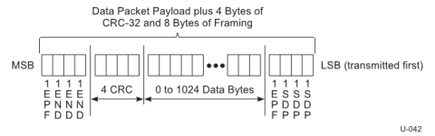
5.1.2 Data Packets and payload
Any data packet starts with a DPPSTART ordered set and is followed by 0-1024 bytes of data. A 4 byte CRC will be computed on the data and appended after the data. This si followed by a DPEND or a DPPABORT (End Data Bad (EDB) symbol) ordered set to denote the end of data. The data payload and framing are tightly packed with no spacing in between.
The figure below shows transfer of 8 bytes of data

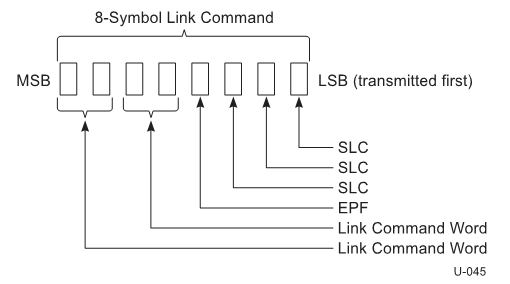
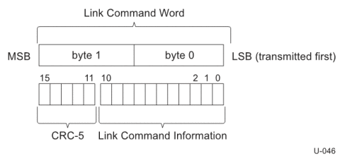
5.1.3 Link Commands
LPM commands are used to ensure link level data integrity, flow control and link power management. Link commands are 4 symbols long with the following constituents
- 4 symbol packet framing ordered sets.
- 2 symbol link command word
- Replica of the link command word for error tolerance
The 16 byte long link command word is formed of 11 bit link command information and 5 bit CRC (CRC5). Link commands are divided into 4 classes based on use case. They are commands for
- Ensuring successful packet transfer
- Link flow control
- Link power management
- Declaring presence in active power state
5.2 Link packet transfer and flow control
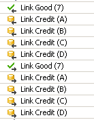
The link layer has a Link buffer that can hold up to 4 unacknowledged (unprocessed) headers. They are circular and are named A through D. The receiver has to inform the transmitter about the availability of a link buffer. This is done in terms of link credit and the process is called “Rx header buffer credit exchange” and uses LCRD_x (x= A through D) link commands. The link commands should be transmitted sequentially. In case of a missing order, retransmission is triggered. This command is embedded in bits [10:9] of the link command word.
Link level acknowledgements are established using LGOOD_n, LBAD and LRTY commands. The three bit header sequence number in the header packet link control word is used to determine the LGOOD_n sequence number. i.e n can have a value ranging from 0 to 7 depending on which header sequence number is being acknowledged. If an LBAD is received, an LRTY is used to signal a retry.
5.2.1 Link Initialization
Link layer initialization of the link includes header sequence number and header buffer credit advertisement. This is done by sending LCRD_x for all available buffers and an LGOOD_n with n=(Rx header sequence number -1)<sub>modulo 8</sub>. More on this will be discussed in the protocol layer
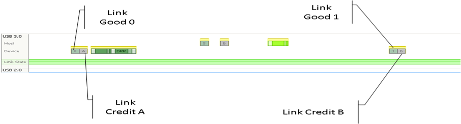
5.2.2 Basic Link Operation
Initially, the header packet sequence counter will be zero at the transmitter and receiver. The LCRD_x will be initialized to LCRD_A at the receiver and the transmitter will also keep track of this. A framed header packet with this sequence packet number of 0 will be sent by the transmitter to the receiver. Upon receiving this with a clean CRC, the receiver will send back a LGOOD_0 back to the transmitter. However, the link credit buffer is not freed since the date in the header packet is not yet processed by the receiver. When the receiver processes the data and the link credit is available, receiver sends a LCRD_A to the transmitter. This will update the next available link credit buffer as LCRD_B. both the receiver and transmitter keeps track of this information.
In case of an error, say a bad CRC on the header packet, then the receiver responds with a LBAD instead of an LGOOD_n. In this case, the transmitter sends an LRTY followed by a retransmission with the same header sequence number. Once this is received correctly, the transmitter sends a LGOOD_0 and a LCRD_A when the link credit buffer is free.
The transmitter can keep transmitting 4 pieces of data without any acknowledgement from the receiver since there are 4 link credit buffers available.
5.2.3 Logical Link Idle and Link power management
In USB 3.0 a logical idle condition of a link is one or more symbol period with no information transfer in the link. The link layer uses LGO_s (s ranging from U1 to U3) to enter the corresponding power state. This is acknowledged by the receiving end with a LAU and in case of rejection, an LXU is sent. LPMA is used in conjunction with LGO_x and LAU to ensure that both ports are in the same state. When a port is in U0 state, and no other data is to be transmitted, it keeps sending the LUP packet every 10us to declare its presence in U0 state
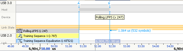
Polling is a part of link training which is achieved with a polling LFPS.
6. Protocol Layer
The protocol layer facilitates the actual data transfer as requested by the host application (driver). The key components of the protocol layer are the different packet and transaction types. USB 3.0 allows a new type of transfer called a stream bulk transfer.
6.1 Transaction Overview
The key difference in USB 3.0 transactions with respect to the USB 2.0 transactions is the fact that Host can schedule one or more OUT transactions while waiting for the completion of current bus transaction. This is partially facilitated by the link credit mechanism discussed in the link layer.
IN tokens in USB 2.0 is replaced by integrating the functionality into the Data Packet Headers (DPH). This gives rise to a burst model data transfer. More details regarding this is discussed later on.
Another key difference from USB 2.0 is that a device can asynchronously send ERDY (without the host explicitly scheduling it) to the host when it is ready for a data transfer.
When the host request for a data transfer, the device can respond with one of the following three packets.
- Data packet : in case if the requested data is available.
- NRDY : in case if the requested data is not available. In this case, the
Device has to send ERDY at a later stage asynchronously to the host when data is available
- STALL : In case of error
The transactions have a direct path between the host and the device and are not broadcast.
6.2 Packet Types
There are 4 main packet types defined in USB 3.0 protocol. They are
- Link Management Packets that travels between a pair of links only
- Transaction Packets between device an host direct path
- Data Packets between device an host direct path
- Isochronous Timestamp Packets that are Multicast on all links
All packets will have a common type field, a Link control word and a CRC 16. Other fields vary with the packet type
The link management packets carry no addressing information and are hence not routable. This is because they traverse between direct partners of the link pair.
A transaction packet can have any of the following sub types
-
ACK
This packet will contain a SeqNum field to specify the next expected packet sequence number. It will also denote the expected number of packets with the NumP field. Thus the ACK doubles as a data synchronization mechanism along with the intended handshaking - NRDY
The packet indicates temporary inability of an endpoint to receive or transmit data. This is used only by a non-isochronous device. - ERDY
Send asynchronously by an endpoint to denote availability of data . - STATUS
Sent by control endpoint to denote start of STATUS stage - STALL
Denotes a halt in deice endpoint - PING and PING_RESPONSE
Used to initialize all links in the path to U0 prior to initializing an isochronous transfer. - DEV_NOTIFICATION
This packet is used by a device in general rather than from a specific endpoint. The device notification can have one of the following sub-types. - FUNCTION_WAKE
Used to identify that caused a remote wakeup in a device - LATENCY_TOLERANCE_MESSAGE
This is an optional feature enabling more power efficient operations. It is used to intimate the Best Effort Latency Tolerance (BELT) value of the device. BELT is the time in ns that a device can wait for a service before experiencing unintentional side effects. They are represented as multiples of 1024, 32768 or 1048576. The BELT value is common for all the configured endpoints. The device has to ensure frequent estimation of its BELT value. The minimum BELT value is 123us and system shall default to a BELT of 1ms for all devices. - BUS_INTERVAL_ADJUSTMENT_MESSAGE
A device might face issues while trying to sync hosts bus interval clock with its internal clock. We need a combination of hardware and software techniques to resolve this. Elastic buffers discussed in the PHY layer is the hardware solution. As for the software part, USB 3.0 specifies a mechanism called bus interval adjustment message that allows a device to increase or decrease the bus interval. The protocol allows the device to request incremental shots no greater than ±4096 at a time to achieve a maximum adjustment of -32768 to +32767. Only one device can control the bus interval at a time. The protocol uses a first come first served mechanism to facilitate this and the address of the controlling device will be indicated in the next isochronous timestamp (ITP) packet.
A data packet header + data packet results as a response to an ACK TP. This eliminates the use of the USB 2.0 IN tokens in USB 3.0. Data payload with a 32 bit CRC immediately follows a data packet header. The data packet will have the sequence number of the first data packet, and data length (excluding CRC32) along with other relevant information.
Isochronous timestamp packets are multicast to all ports in U0. Timing values are accurate to 125us and contain a delta field specifying a time delta from the previous bus interval boundary.

6.3 Transactions
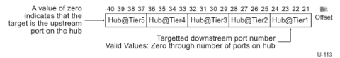
USB 3.0 transactions are mostly point to point and not be broadcasted. This is facilitated by a 20 bit routing string in every downstream port (DSP) directed packets. This is generated by concatenating the DSP numbers (4 bit per hub) for each hub traversed to reach a hub. (This limits the number of ports to 15 in a hub). This is added by the hub and the device sees it as reserved field.
USB 3.0 transactions are very much like the USB 2.0 transactions. However, there are few enhancements incorporated. To understand those, we will look into the details of a bulk transfer.
6.3.1 Burst transactions
USB 3.0 allows a device to transmit and receive packets without waiting for an acknowledgement. This is the burst mode of transfer. The number of packets per burst inintimated in the endpoint companion descriptor at enumeration.
During a transaction, the remaining number of packets that can be received in a burst can be calculated from the NumP field of the latest acknowledgment TP. However, all packets need explicit acknowledgement and the NumP field should not be decremented by more than 1 at once. Also, in a burst, all packets except the last will have maximum size of data.

6.3.2 Bulk transaction
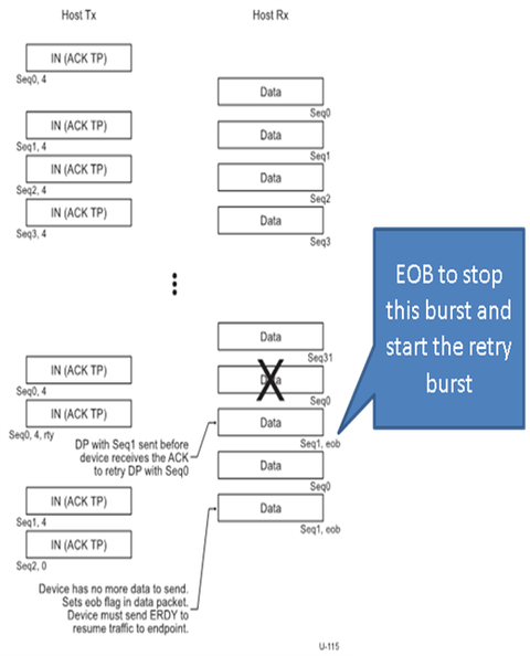
An ACk transaction packet implicitly acknowledges the last received Data Packet (DP) with the previous SeqNum as being successfully received by the host. It also serve similar to the USB 2.0 IN tole and asks for the next NumP DPs with starting at SeqNum. In case of an error, an ACK TP with the first erroneous DP SeqNum and RTY bit set will be sent. This means that even though subsequent DPs in the burst where received correctly, they need to be re transmitted.
The first transmitted packet will have the SeqNum set to 0. This value rolls over to 0 after 31. If device donot have sufficient number of data packets as requested the last packet of the burst will have the EndOfBurst bit set to one.
In case of a bulk OUT transaction, host sends a DPH followed by a DPP to the device. If the device is not ready to receive data, it responds with a NRDY . Later, when the device is ready to accept data, it asynchronously sends the ERDY packet.
6.3.3 Bulk Stream Protocol

USB 3.0 defines a new protocol built over the USB 3.0 bulk transfer protocol that expands the usability of a bulk endpoint. The gist of the bulk stream protocol is to extend the number of host buffers accessible by an endpoint from 1 up to 6553. i.e, large amounts of data can be transferred in parallel without wasting time form the data to be processed from the EP buffers. The protocol follows the semantics of the bulk pipe and thus packets in a stream pipe cannot be distinguished from a normal bulk packet except from the “Current Stream ID”.
Stream pipes are maintained by a stream protocol state machine


Leave a comment